AI-FORM Incremental Sheet Forming
Toolpaths Design and Process Simulation Software
AI-FORM ISF Toolpath is a software product designed for the purpose of creating, editing and visualizing incremental sheet forming (ISF) toolpaths.
AI-FORM ISF has been integrated into the AI-FORM user's environment, includes the part base analysis, features evaluation, ISF toolpaths design, checking and modification, toolpath export and many other useful functions.
The SPIF, TPIF and DSIF are supported by AI-FORM ISF software.
AI-FORM ISF Simulation is the twins software product as ISF Toolpath. It is based on the AI-Form FEM solver and user's environment to simulate the ISF process.
Many breakthrough technologies have been acquired in the AI-Form ISF simulation package, to reduce the simulation lead time and improve the accuracy of the result.
Multi-stage forming and multi-process forming (i.e stretch forming plus ISF process) are supported by the ISF simulation.

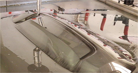
3D Part (Engine cover)
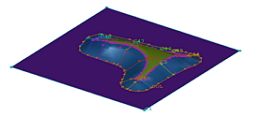
Die Face Design
Toolpath (PSIF)
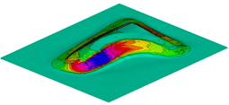
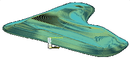
Thickness
Main Features of AI-FORM ISF
SALIENT FEATURES (Toolpaths)
- Support SPIF, TPIF, DSIF process
- Support multi-features and complex shapes
- Z-level and continue Spiral section cut
- Automatic fill curve function
- Database of machine, tool pin and link design
- Generate NC code and CSV text file
- Toolpath checking and visualization
- Join multi-toolpaths together
- Quick coordinator editor of toolpath
- CAD model and mesh base toolpath generator
- Part base section cut checking
- Part radius checking for tool pin selection
- Full chain from part to toolpaths (Addendum design)
SALIENT FEATURES (Simulation)
- Easy to setup and fully integrated
- Breakthrough technology to speed-up the ISF simulation ( Tens time faster than traditional FEM code with same accuracy)
- Virtual multi-tools approach
- Support multi-stages simulation
- Support multi-process mapping
- Effective parallel computing
- Accurate contact calculation
- Support all ISF process
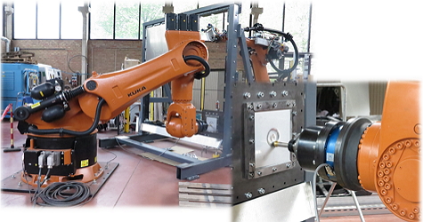
ISF FORMING PROCESS
Incremental sheet metal forming is a forming process for the manufacturing of complex components in small quantities. In comparison to conventional metal forming methods complex tools can be dispensed. This reduces tool costs and the time to the first finished part. These advantages predestine incremental sheet metal forming for number of pieces in the range of 1 to 1,000 parts.
ISF TOOLPATHS DESIGN
The generation of toolpaths in ISF presents rather unique challenges compared to conventional toolpath design, as is commonly found in CNC machining. In CNC machining, it is safe to assume that material will be removed/cut in and around the tool’s current location, which in CAD terms, can be captured using a simple negative Boolean operation between the tool and solid work piece.
On the other hand, the metal sheet in ISF bends, locally thins, stretches, and springback during the forming process which are all challenging to predict and account for during toolpath generation.
AI-FORM ISF Toolpaths uses various novel procedures, to overcome some of the aforementioned challenges and produce reliable toolpaths specific to the ISF process.
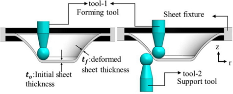
Forming process of SPIF (left) and DSIF (right)
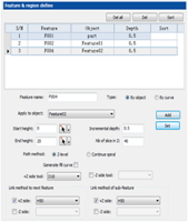
Toolpath design interface
ISF FEM SIMULATION
The FEM has been extensively utilized to better understand the fundamental mechanics that differentiate various ISF setups and toolpath techniques.
- For a long time, numerically simulating ISF can be very demanding and time consuming, mainly due to the many nonlinearities inherent to ISF as well as the range of length scales that must be considered.
- Related to length scales, a typical blank is usually hundreds of millimeters in width, but perhaps only one millimeter thick.
- Taking all of these challenges into account, it is of no surprise that the industrial companies are looking for a fast, high-fidelity simulations tools of ISF.
The objectives of the simulations are as follows:
- Geometric accuracy and surface finish. To generate state-of-the-art toolpaths for SPIF, TPIF, and DSIF.
- Excessive thinning and fracture. It is necessary to gain a deeper understanding of the intricate, localized mechanics of the DSIF process.
- Towards controlling and optimizing the ISF process based on the simulation result.